I was pleasantly surprised that the machine rebuild went fine - there's definitely some more fine tuning to be done, but overall it still works well and I didn't have to replace any of the major parts. I did end up replacing the router, mostly because I wanted everything to be native 240v - I didn't like the idea of running a router from a transformer for long jobs.
Here's some in-progress photos:


 I did add a few upgrades/changes during the rebuild. Something that was missing from the original setup were limit switches. I found the Xylotex limit switch suggestion on the Solsylva site (this has been down for years, but the content is available on web.archive.org here). I 3d printed the limit switch mounts (3 different designs).


The z-axis limit trigger is just a bit of Lego glued onto the z-axis lead nut...


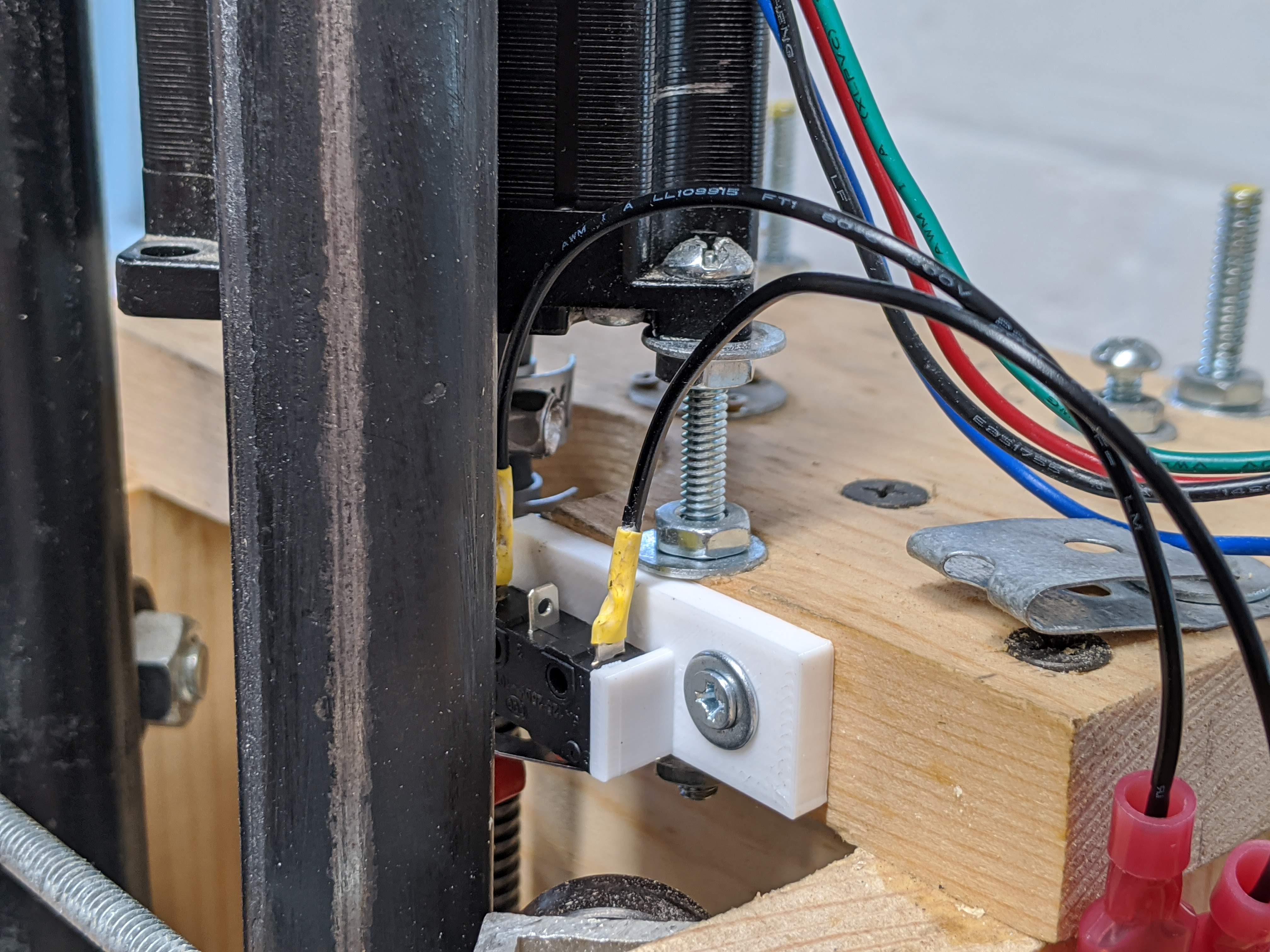


All the limit switches are wired in series using speaker cable.
The z-axis limit trigger is just a bit of Lego glued onto the z-axis lead nut...
These work really well and it means that I can automatically (and consistently) home the machine. Importantly, it also means that I don't have to worry about causing damage if I accidentally try to move outside of the machine limits (which I definitely did a few times when using it in the US).
I had to use a different mounting method for the Makita router. I found a few mounts on thingiverse that looked like they would 'almost' work - I ended up adapting this one for my setup (I extended and flattened the mounting point so I could attach it directly to the wood). This took a few iterations before it worked well - the detachable dust shoe (from the original designer) is a nice touch!

Now for some random makey makey pics.
First attempt at dust extraction - not ultimately useful, but the cut of the piece is quite pleasing.


Soundwave design for my eldest daughter (her favourite transformer).

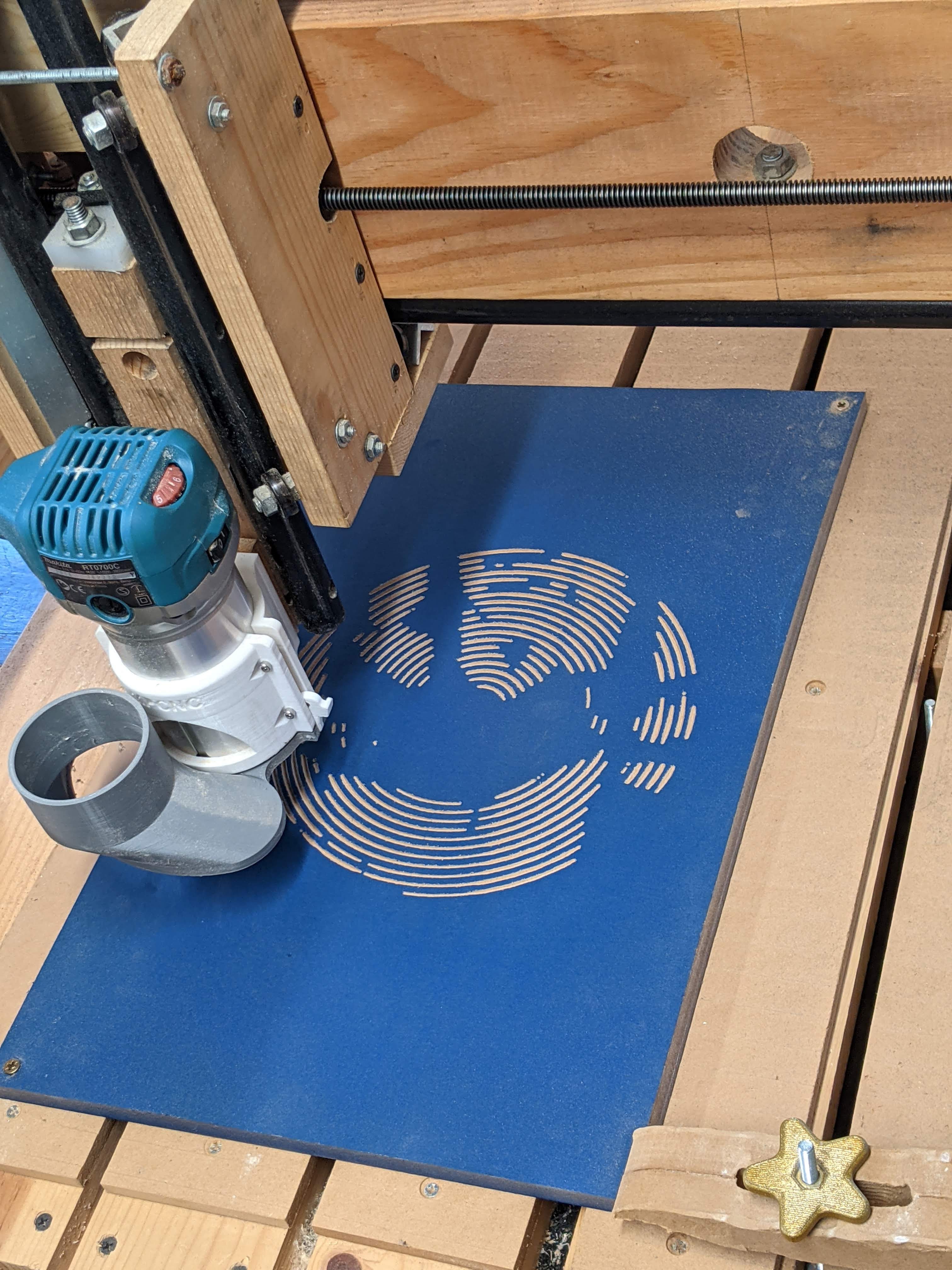

Halftone map of the world for my mum's birthday. I used Jason Dorie's Halftoner program to create this (and the above soundwave image).


Finally, some dice boxes I'm still slowly working on.


